Beginners Guide to use Small DC motor and LED with Arduino UNO
ABOUT THIS PROJECT
This project is the demonstration of how a dc Toy motor and led can be operated using Arduino Board.
here we will simulate as well as do the hardware and understand the basic idea.
BACKGROUND
Now, Before starting with the project let's see the list of Components and understand them.
The following components will be required to build the project:
- Arduino UNO R3 board
- Small DC motor
- Bread Board
- LED - 1 unit
- Connecting Wires
Arduino UNO R3
The Arduino Uno is an open-source microcontroller board based on the Microchip ATmega328P microcontroller and developed by Arduino.cc. The board is equipped with sets of digital and analog input/output (I/O) pins that may be interfaced to various expansion boards (shields) and other circuits.
Arduino UNO board
Small Dc Motor
A direct current (DC) motor is a type of electric machine that converts electrical energy into mechanical energy. DC motors take electrical power through direct current and convert this energy into mechanical rotation.
small DC motors are used in tools, toys, and various household appliances.
LED
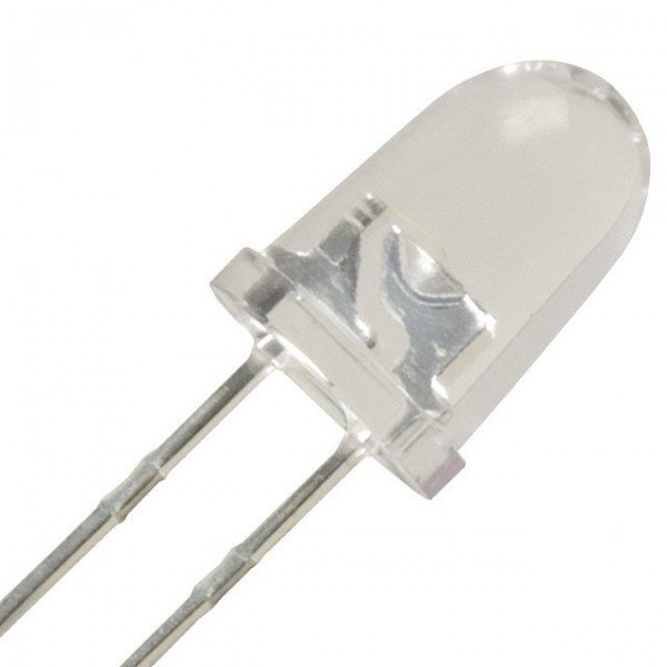
A light-emitting diode(LED) is a semiconductor light source that emits light when current flows through it.
OBJECTIVES
- we will understand how we can blink a LED with our controller.
- we will understand how we can control a small dc motor with our controller.
- we will control the LED and dc motor together.
Arduino IDE setup
To get started we need to have IDE for programming purposes.
LED blinking
To understand this, we can use the built-in LED that most Arduino boards have or connect a led externally with a 220 ohms resistor in series.
Connections
- Connect cathode terminal of led to ground
- Connect anode to any digital pin(eg. pin 13 ) with a 220 ohm resistor in series as shown.
void setup()
{
  pinMode(13, OUTPUT);
}

void loop()
{
  digitalWrite(13, HIGH);
  delay(1000); // Wait for 1000 millisecond(s)
  digitalWrite(13, LOW);
  delay(1000); // Wait for 1000 millisecond(s)
}
CODE EXPLANATION
void setup()
The setup() function is called when a sketch starts.
here we are configuring pin 13 as an output pin using pinMode() function.
void loop()
The loop is another function that Arduino uses as a part of its structure. The code inside the loop function runs over and over as long as the Maker Board is turned on.
The digitalWrite() function is used to write a HIGH or a LOW value to a digital pin.
and delay() function makes the program wait until moving on to the next line of code when it encounters this function.
NOTE: For delay function parameter passed is in milliseconds.
Simulation Video
Small DC motor Control
It consist of two terminal ,one positive and one negative. If you connect these two leads directly to a battery, the motor will rotate.If you switch the leads, the motor will rotate in the opposite direction.
Warning - Do not drive the motor directly from arduino boards pins. This may damage the board. Use a driver circuit or an IC , Here I have shown for demonstration and understanding purpose .
Connection:
- Connect one terminal of motor to any of the digital pin.
- Connect other terminal to ground.
void loop()
Using digitalWrite() function we are writing pin 12 as HIGH or LOW.
Simulation Video
LED and DC motor Control with a push botton
To Understand effectively we will
- Turn on LED for 5 seconds then turn it off
- Then motor will run for 20 seconds and stop
- At last LED will turn on again for 5 seconds
Connections:
- Repeat the same connections for both LED and motor as demonstrated above
- Connect one of the terminal of push botton to 5V pin in Arduino
- Connect other pin to a 220 ohm resistor and any of the digital pin as shown below
int val = 0;
void setup()
{
  pinMode(13, OUTPUT);
  pinMode(12, OUTPUT);
  pinMode(8, INPUT);
}

void loop()
{
  val = digitalRead(8);
 if (val == HIGH )
  {
  digitalWrite(13, HIGH);
  delay(500);
  digitalWrite(13, LOW);
  delay(500);
  digitalWrite(13, HIGH);
  delay(500);
  digitalWrite(13, LOW);
  delay(500);
  digitalWrite(13, HIGH);
  delay(500);
  digitalWrite(13, LOW);
  delay(500);
  digitalWrite(13, HIGH);
  delay(500);
  digitalWrite(13, LOW);
  delay(500);
  digitalWrite(13, HIGH);
  delay(500);
  digitalWrite(13, LOW);
  delay(500);
  digitalWrite(12, HIGH);
  delay(20000);
  digitalWrite(12, LOW);
  digitalWrite(13, HIGH);
  delay(500);
  digitalWrite(13, LOW);
  delay(500);
  digitalWrite(13, HIGH);
  delay(500);
  digitalWrite(13, LOW);
  delay(500);
  digitalWrite(13, HIGH);
  delay(500);
  digitalWrite(13, LOW);
  delay(500);
  digitalWrite(13, HIGH);
  delay(500);
  digitalWrite(13, LOW);
  delay(500);
  digitalWrite(13, HIGH);
  delay(500);
  digitalWrite(13, LOW);
  delay(500);
  exit(0);
}

}
CODE EXPLANATION
We need to declare a variable first and set it to low
void setup()
here we are configuring pin 12, pin 13 as output and pin 8 as input pin using pinMode() function.
void loop()
For using the push button first we are reading the value (HIGH or LOW) of pin 8 using digitalRead() function and if it is HIGH(When the user will push the button it will be HIGH unless it will remain LOW) we are then writing pin 13 and pin 12 as HIGH or LOW using digitalWrite() and delaying using delay() function.
Simulation Video
HARDWARE
Conclusion
As you have understood the circuit and basic programs, Now you can modify the program try different things on your own.
If you haven’t set up Arduino IDE on your local machine. check out the article on


Comments
Post a Comment